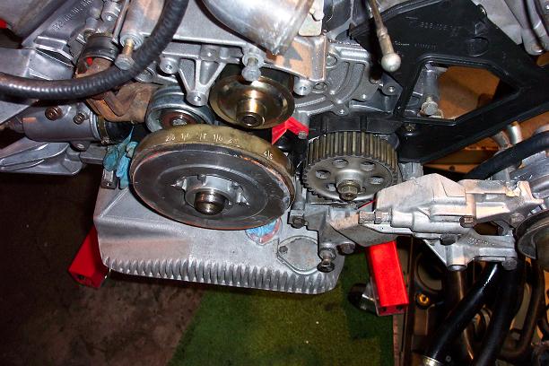
The next step was to install the cams. Here's the step by step process. First, rotate the crank to 45 degrees before top dead center (referred to as "TDC" in the workshop manuals)
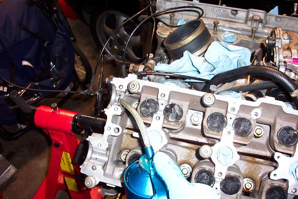
Next, lubricate the bearing surfaces. I used Royal Purple motor oil.
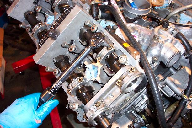
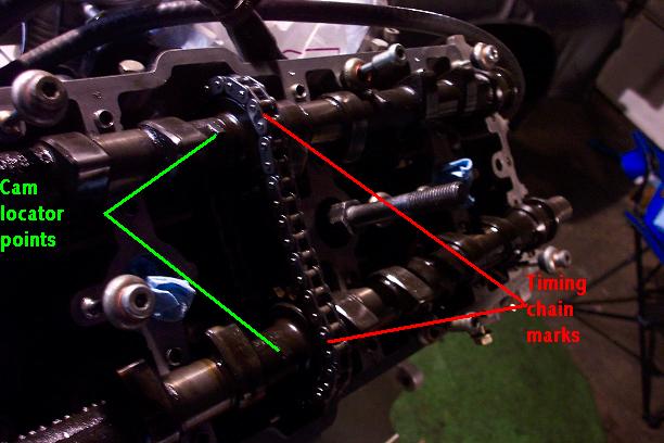
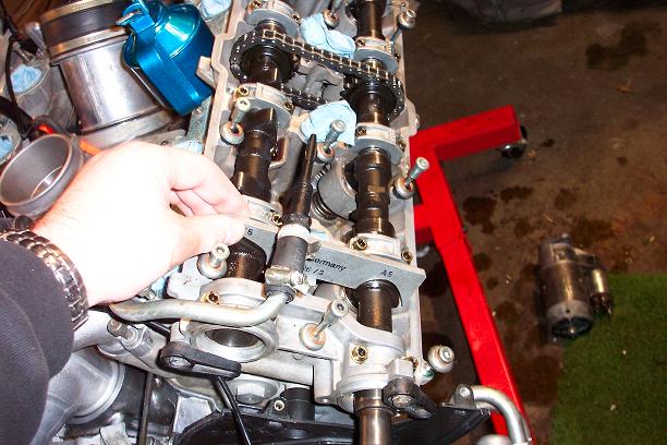
Once the bearing surfaces are all lubricated, take the cams and locate the markings "A 1-4" (exhaust cam for cylinders 1 through 4) and "E 1-4" (intake cam for cylinders 1 through 4). Cylinders 1 through 4 are on the passenger side of the engine. On each cam, there is an indicator mark to the left of the chain gear. The timing chains should have 2 differently-colored links that have 5 links between them. My new chains did not have the marks so I use a black marker to put them on after laying the new chains next to the old ones. Lay the cams (with the chains installed) onto their proper locations, which are easy to figure out because the ends of the cams fit neatly into the bearing end caps. In this picture you can also see one of the bolts for "Special Tool 9226" which are installed in the spark plug holes for cylinders 2 and 4.
The bolts for Special Tool 9226 are 19mm. Here's another picture of how they are fastened to the spark plug holes.
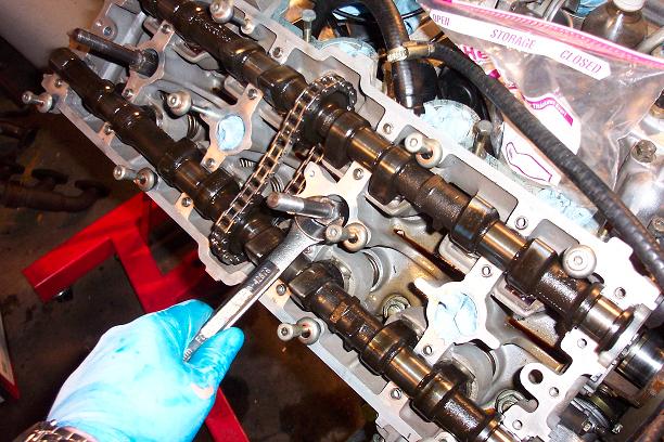
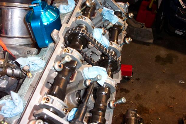
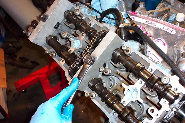
Here you can see Special Tool 9226 mounted on the bolts. Again, a 19mm nut holds it in place. Turn the nut on top of each of the two tools gradually and evenly so that the pressure from the valve springs doesn't exert more force on one end of the cam than the other at any time. This is necessary to prevent the cams from bending.
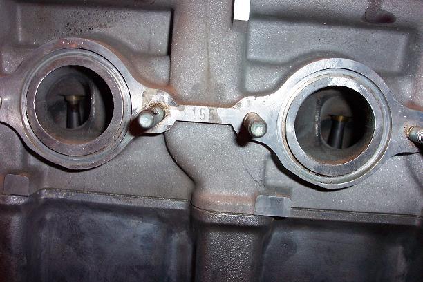
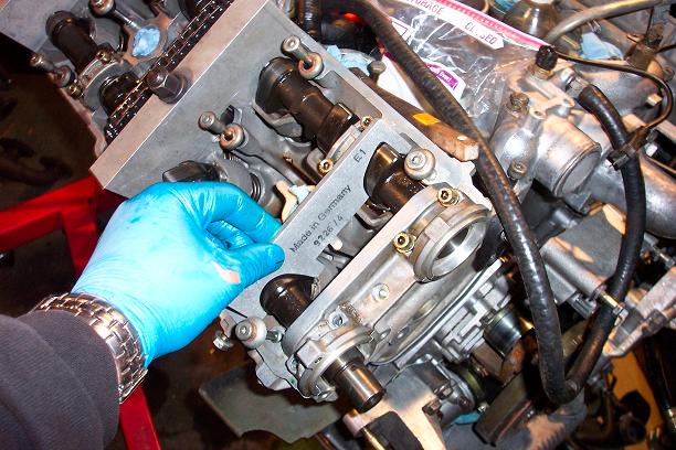
Now that Special Tool 9226 is installed, get your bearing caps ready. Each of the caps is numbered to correspond to the head they are from as well as the position on the head where they are supposed to be installed. The number on each head is located between the middle exhaust ports. Here you can see this head's number, 155.
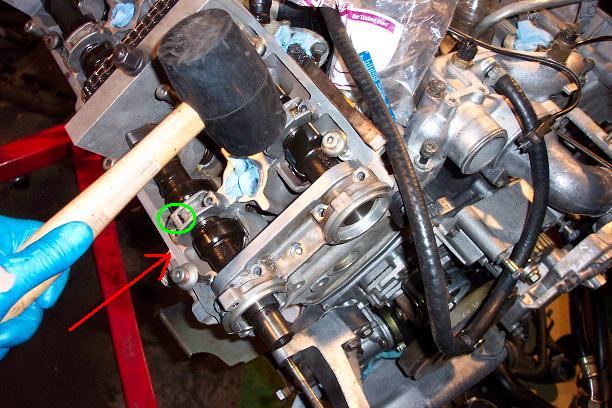
Install the bearing caps (except where Special Tools 9226 are located). Make sure the number on each cap corresponds to the number on the head for each cap's location. The number on the cap should ALWAYS face outward as seen in this picture. I've circled where the bearing cap number is located and the red line points to where the cap number is found on the head. For example, the bearing cap for cylinder 1 at the bottom would be numbered 1-155 (remember 155 is the head's own number) and the spot where the cap is installed will have a "1" etched into it. If you have trouble getting the caps on, you can try gently tapping them into place with a rubber mallet.
Special Tool 9226/4 placed onto the cam lobes for cylinder 1 shows that the cams are aligned correctly. Special Tool 9226/3 sets up on cylinder 5 (driver's side) to show that those cams are also aligned correctly.
Here's Special Tool 9226/3 on the lobes for cylinder 5.
Once you know the cams are aligned correctly, torque the bearing cap nuts down to 10nm (7 ft. lbs.). Once you've torqued down the caps, you can remove Special Tool 9226 and install the bearing caps for those locations, too. Now all the caps are installed and torqued to factory settings.